 TSurface3D defines a 3D NonUniform Rational BSpline (NURB) surface of arbitrary order that can be trimmed with 2D loops (TGLoop). NURBS let you represent exact boundaries for all common quadratic shapes such as cones, cylinders, spheres, tori, rotation surfaces, linear surfaces, rounded boxes, rounded cylinders and simple flat surfaces in 3D. By manipulating the knot vectors, multiple (C0) discontinuity can be introduced in either parametric direction to form an arbitrary shape. Curve order and knot vectors are described in Chapter 4.
| TSurface3D | ClearTrim | GetPoints | Refine | |
| DragPosition | GetSectionOfSurface | RefineToBezier | ||
| Evaluate | GetTrim | RefineUniform | ||
| GetIsoCurve | InsertKnot | RefineToPinned | ||
| GetKnot | IsBezier | ReverseDirection | ||
| GetKnots | IsConsistent | SetKnotScheme | ||
| GetMinParameter | IsPinned | SetKnots | ||
| GetMaxParameter | MakeCompatible | SetPoint | ||
| GetNumberOfPoints | MakeDiscontinuity | SetPoints | ||
| GetNumberOfKnots | MoveKnot | SetOrder | ||
| GetOrder | NearestParametric | SetTrim | ||
| GetPoint | RaiseOrder | SwapUandV | ||
| TGSurface3D | ApproximateLowerOrder | GetNextDiscontinuity | ||
| IsEmpty | GetSectionOfCurve |
Operations that work on a specific parametric direction use the enumerated values kvDirection and kuDirection of type ESurfaceDirection to specify the direction in which to operate. A surface is framed with isoparametric lines whose spacing can be adjusted through the bundle.
The control points Vi,j are indexed with i proceeding across in the v parametric direction, and j proceeding across in the u parametric direction. If the surface is oriented with the parametric direction in v clockwise from the parametric direction in u at the V0,0 corner of the control mesh, then the outside of the surface is facing you; that is, the outside shader is used to render that side of the surface. (Inside and outside surfaces and shaders are described in Chapter 16.) Figure 164 Parametric space
A surface has two parameters, u and v. One parameter defines an isoparametric line across the surface, and the other parameter can be thought of as defining a point on that line. An Isoparametric line is a line that is drawn with one of the surface parameters (u or v) held constant.
The control points for a surface are specified with a (onedimensional) TGRPoint3DArray. The mapping from the control mesh point Vi,j to an array index Ak for an n by m mesh is Ai*n+j = Vi,j. In other words, the array is stored as a sequence of rows of control points in the u direction.

Trimming loops
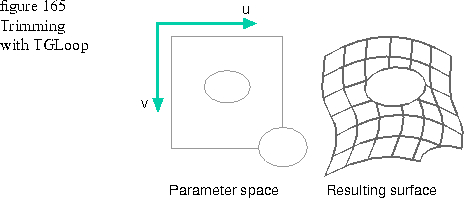
You can use one or more trimming loops to remove parts of the surface to create an interesting shape. Trimming loops are defined in the parametric space of the surface. The x coordinate of a point on the TGLoop maps to u in parameter space, and y maps to v. If the trimming curve exceeds the boundary of the surface, then the corresponding edges of the surface are trimmed away. An empty trimming loop is specified by the constant kNullLoop.
The trimming loops shown in Figure 165 are the two elliptical shapes on the left side of the figure. By combining surfaces and using trimming loops, you can create simple flat shapes like the one on the right side of the figure.

Code example
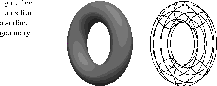
The following code uses a surface geometry to create the torus shown in Figure 166. The torus on the left is drawn using the default color, shading, and texture map of the port. The torus on the right is drawn as a wireframe. The camera has been moved to TGPoint3D( 1440, 0, 1440) to show the torus from a different angle. See Chapter 12 for example code that moves the camera and resets the default values in the scene bundle. See Chapter 17 for more information on scene bundles and cameras.

1  double majorRadius = 150;
2  double minorRadius = 50;
3
4  TGSurface3D torus( 3, 3, 9, 9 );
5
6  GCoordinate xvalues[] = { 0.0, -1.0, -1.0, -1.0, 0.0, 1.0, 1.0, 1.0, 0.0 };
7  GCoordinate yvalues[] = { 1.0, 1.0, 0.0, -1.0, -1.0, -1.0, 0.0, 1.0, 1.0 };
8  GCoordinate zvalues[] = { 0.0, 1.0, 1.0, 1.0, 0.0, -1.0, -1.0, -1.0, 0.0 };
9  GCoordinate offsets[] = { -1.0, -1.0, 0.0, 1.0, 1.0, 1.0, 0.0, -1.0, -1.0};
10
11  torus.SetKnotScheme( TGSurface3D::kuDirection, TGCurve3D::kBezier );
12  torus.SetKnotScheme( TGSurface3D::kvDirection, TGCurve3D::kBezier );
13
14  long i, j;
15
16  GCoordinate r2over2 = SquareRoot( 2.0 ) / 2.0;
17  GCoordinate weight;
18
19  for (i = 0; i < 9; i++)
20  {
21      for (j = 0; j < 9; j++)
22      {
23          weight = ((j & 1) ? r2over2 : 1.0) * ((i & 1) ? r2over2 : 1.0);
24          // Weights are pre-multiplied with the x, y and z values
25          torus.SetPoint( i, j,
26              TGRPoint3D(
27                  xvalues[j]
28                      * (majorRadius + offsets[i] * minorRadius)
29                      * weight,
30                  yvalues[j]
31                      * (majorRadius + offsets[i] * minorRadius)
32                      * weight,
33                  (zvalues[i] * minorRadius) * weight,
34                  weight ) );
35      }
36  }
37
38  thePort.Draw( torus );
Lines 6 through 9: Define the shape of a unit torus centered about the origin.
Lines 11 and 12: Define a piecewise Bézier knot vector for a quadratic curve with four segments.
Lines 14 through 34: Calculate the size and surface area of the torus.
Line 38: Draw the torus using the default fill. You could pass a frame bundle to the port to draw the torus as a wireframe.