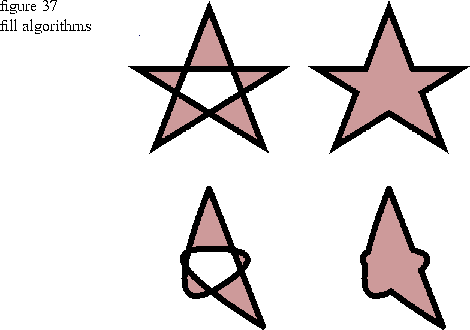
Figure 37
shows two polygons on the top and two loops on the bottom. The left polygon and loop have their EOFill flag set to True, and the right polygon and loop have their EOFill flag set to False. If the EOFill flag is True, the polygon or loop is filled with an evenodd rule, and if the EOFill flag is False, a nonzero winding rule is used. These rules are described below.

Top-left polygon
aPolygonGeometry.SetEOFill( TRUE );
thePort.Draw( aPolygonGeometry, aBundle );
Top-right polygon
aPolygonGeometry2.SetEOFill( FALSE );
thePort.Draw( aPolygonGeometry2, aBundle );
Bottom-left loop
TGLoop aLoop( 2, aLoopArray, TRUE );
thePort.Draw( aLoop, aBundle );
Bottom-right loop
TGLoop aLoop2( 2, aLoopArray, FALSE);
thePort.Draw( aLoop2, aBundle );
The points used in aPointArray for the first polygon are the same points that were used to create the star polygon in Chapter 2. Values are added to the x and y coordinates as needed to position the polygons and loops in the view so that you can see them together.
The loops are created with a curve order of 3. If the curve order were 2, the loops would appear identical to the polygons because polygons have a curve order of 2. Giving the loops a curve order of 3 makes them appear round. Increasing the curve order increases the roundness. See the heading "Curves, loops, and knot vectors" on page 79 for details on curve order.