![]()
![]()
![]()
The graphic and geometry classes have a number of constructors from which you can choose. These examples construct graphics directly from the computational geometry and point array classes described under the heading "Underlying geometry classes" on page 36 to help you understand how geometries are built.
In the rectangle example, the drawing is done by calling the TGrafPort::Draw function. In the other examples an MGraphic derived class is used to create the shape and the MGraphic::Draw function is called instead. Using the geometry class directly and passing it to the TGrafPort::Draw function is a fast way to draw that uses very little overhead. You would take this approach when you don't need the functionality provided by MGraphic. TGrafPort::Draw accepts an optional transformation matrix and attribute bundle.
You would use an MGraphic derived class to arrange simple graphics into a group or picture, or to use the MGraphic transformation functions to transform the MGraphic derived class without using a matrix. See Chapter 19 for information on drawing ports, and see the heading "2-D transformation matrix" on page 38 for information on the 2-D transformation matrix.
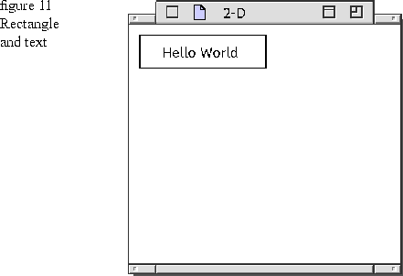
Draw a rectangle
around some text
This DrawContents implementation draws a text string in the view and puts a rectangle around the text string. Figure 11 shows how the rectangle and text look at run time. The origin (0,0) is in the upper-left corner of the view. Positive x values increase to the right, and positive y values increase as you go down.
1  void DrawContents( TGrafPort& thePort ) const
2  {
3      TGRect aRectangle( TGPoint( 10, 10 ), TGPoint( 125, 40 ) );
4      thePort.Draw( aRectangle );
5
6      TStandardText theText( "Hello World" );
7      TTextDisplay  theDisplayedText( theText );
8      theDisplayedText.SetOrigin( TGPoint( 30, 30 ) );
9      theDisplayedText.Draw( thePort );
10  }
Lines 3 and 4: The rectangle is created from the computational geometry TGRect and the default bundle. The default bundle draws the rectangle with a black hairline frame and no fill. Chapter 4 shows how to create a rounded rectangle using the loop geometry.
The rectangle instantiation specifies two parameters of type TGPoint. The first parameter, (10, 10) specifies the upper-left corner of the rectangle, and the second parameter (125, 40) specifies the bottom-right corner of the rectangle.
Lines 6 through 9: This text string "Hello World" is already present in the HelloWorld sample application. It instantiated as a TStandardText. TStandardText is passed to the constructor of TTextDisplay to display the standard text string in a single, uneditable line using the system font. The first letter of the text string begins at TGPoint (30, 30).
TGPoint is a computational geometry class that represents x and y coordinate values in 2-D space. A TTextDisplay text string cannot be transformed. If you want a text string that can be transformed, use TTextGraphic. TTextGraphic descends from MGraphic, but is described as part of the Text system. See that volume for more information.
You can use TTextDisplay member functions to specify text attributes such as type face, point size, and color of the text string. The following code fragment could be added to the DrawContents function above to change the text string to the Chicago type face using 12 point type and a cyan fill.
Lines 3 and 4: The ellipse is created from the computational geometry
NOTE
Since no bundle is created and used in this code, the default bundle is supplied by the drawing port. This default bundle draws the ellipse with a black hairline frame and no fill. When an ellipse is constructed from a rectangle, the sides of the ellipse bisect the midpoints of the sides of the rectangle.
Lines 3 through 13: The polygon geometry is created by instantiating a TGPolygon and using the Append function to add points. The line segments draw in the order you append them. The line between (70, 40) and (50, 80) is drawn first.
Line 14: The frame bundle (polyBundle) defines a black frame in the red, green, and blue (RGB) color space by specifying the values TRGB( 0, 0, 0 ), a solid pen width of 5.0 world-coordinate units to frame the geometry border, and kCenterFrame that centers the 5.0 wide black frame over the geometry border. The polyBundle is sent to the drawing port where its settings override the settings in the default bundle. Chapter 7 has more details on colors and frames.
Line 16: The star graphic is created from the geometry and polyBundle by using polyBundle to create a TGrafBundle so that it can be used in the star constructor.
This code fragment calls the MGraphic::TranslateBy function to translate the star 90 world-coordinate units in the x direction and 20 in the y direction. The TGPoint parameter provides x and y values that are added to the points of the star using matrix multiplication. Several transformation operations on one graphic result in successively multiplying the points of the 2-D graphic.
Create the text string
TTextDisplay attributes
  theDisplayedText.SetFont( TToken ( "Chicago" ) );
  theDisplayedText.SetPointSize( 12 );
  theDisplayedText.SetColor( TTextColorStyle::GetCyan() );
Change the rectangle to an ellipse
This DrawContents implementation changes the rectangle to an ellipse. Figure 12 shows how the ellipse and text look at run time.
1  void DrawContents( TGrafPort& thePort ) const
2  {
3      TEllipse ellipse( TGRect( TGPoint( 10, 10 ), TGPoint( 125, 40 ) ) );
4      ellipse.Draw( thePort );
5
6      TStandardText theText( "Hello World" );
7      TTextDisplay  theDisplayedText( theText );
8      theDisplayedText.SetOrigin( TGPoint( 30, 30 ) );
9      theDisplayedText.Draw( thePort );
10  }
Create the ellipse
TGRect and the default bundle. The first TGRect parameter defines the upper-left corner, and the second parameter defines the lower-right corner of
the rectangle.  You could have constructed the TEllipse with the TGEllipse geometry class. A TGEllipse can be passed to a TGCurve with two angle values to construct a curve from an ellipse and two angles (see Chapter 4 for an example); and a TGEllipse can be used with an area geometry to create an arbitrary shape (see Chapter 5 for an example).
 Default bundle
Draw a star with a simple bundle
This DrawContents implementation creates a star polygon (TPolygon) from a polygon geometry (TGPolygon). Figure 13 shows how the star looks at run time. 
1  void DrawContents( TGrafPort& thePort ) const
2  {
3      TGPolygon aPolygonGeometry;
4      aPolygon.Append( TGPoint( 70, 40 ) );
5      aPolygon.Append( TGPoint( 50, 80 ) );
6      aPolygon.Append( TGPoint( 10, 90 ) );
7      aPolygon.Append( TGPoint( 45, 110 ) );
8      aPolygon.Append( TGPoint( 25, 155 ) );
9      aPolygon.Append( TGPoint( 70, 130 ) );
10      aPolygon.Append( TGPoint( 115, 155 ) );
11      aPolygon.Append( TGPoint( 95, 110 ) );
12      aPolygon.Append( TGPoint( 130, 90 ) );
13      aPolygon.Append( TGPoint( 90, 80 ) );


14      TFrameBundle frameBundle( TRGBColor( 0, 0, 0), 5.0 );
15
16      TPolygon* star = new TPolygon(  TGPolygon( aPolygonGeometry,

               new TGrafBundle( frameBundle );
17      star->Draw( thePort );
18
19      delete star;
20      delete polyBundle;
21  }
Create the star geometry
Create the bundle
Create the star graphic
Transform the star
MGraphic provides the common transformation operations of translate (move to another location), rotate (reorient by turning at an angle), and scale (resize by making larger or smaller). Figure 14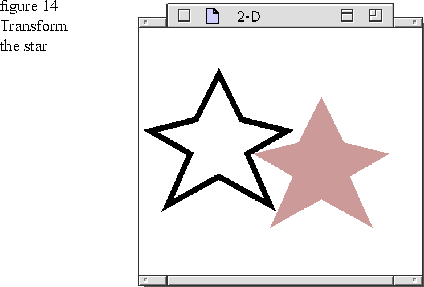
To transform a 2-D graphic, instantiate a 2D matrix (TGrafMatrix) and call the appropriate functions, or as in the code fragment above, call the MGraphic transformation functions. See Chapter 3 for information on the MGraphic functions. See the heading "2-D transformation matrix" on page 38 for information on the TGrafMatrix functions and matrix multiplication. star->TranslateBy( TGPoint( 90,20 ) );
TGrafBundle* fillBundle = new TGrafBundle( TFillBundle( TRGBColor( .75, 25, 25 ) ) );
star->AdoptBundle( fillBundle );
star->Draw( thePort );
Draw two stars as a group
A 2-D group lets you combine any number of 2-D graphics to make a more complex shape. The shapes within the group function as a single unit for as transformations and hit testing. Each star graphic has its own frame bundle to define its own color and line-width specifications. Because TGraphicGroup is an MGraphic, the group could also have an attribute bundle that is applied to all children. See Chapter 10 for more information and groups, and see Chapter 3 for more information on transformations and hit testing. Figure 15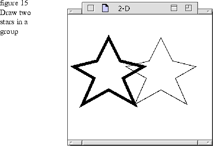
Lines 5 through 15: The first star is created by instantiating a TGPolygon and appending the points. 1 void DrawContents( TGrafPort& thePort ) const
2 {
3 static const long numPoints = 10;
4
5 TGPolygon aPolygonGeometry;
6 aPolygonGeometry.Append( TGPoint( 70, 40 ) );
7 aPolygonGeometry.Append( TGPoint( 50, 80 ) );
8 aPolygonGeometry.Append( TGPoint( 10, 90 ) );
9 aPolygonGeometry.Append( TGPoint( 45, 110 ) );
10 aPolygonGeometry.Append( TGPoint( 25, 155 ) );
11 aPolygonGeometry.Append( TGPoint( 70, 130 ) );
12 aPolygonGeometry.Append( TGPoint( 115, 155 ) );
13 aPolygonGeometry.Append( TGPoint( 95, 110 ) );
14 aPolygonGeometry.Append( TGPoint( 130, 90 ) );
15 aPolygonGeometry.Append( TGPoint( 90, 80 ) );
16
17 TFrameBundle frameBundle( TRGBColor( 0, 0, 0), 5.0 );
18 TGrafBundle* polyBundle = new TGrafBundle( frameBundle );
19 TPolygon star = new TPolygon( TGPolygon( aPolygonGeometry ), polyBundle );
20
21 TGPolygon aPolygonGeometry2( aPolygonGeometry );
22
23 THairlineFrameBundle hairlineBundle( TRGBColor( 0, 0, 0) );
24 TPolygon star2 = new TPolygon( TGPolygon(aPolygonGeometry2 ),
25 new TGrafBundle( hairlineBundle );
26 star2->TranslateBy( TGPoint( 90, 0 ) );
27
28 TGraphicGroup* starGroup = new TGraphicGroup();
29 starGroup->AdoptFirst( star );
30 starGroup->AdoptLast( star2 );
31
32 starGroup->Draw( thePort );
33 delete starGroup;
34 }
Line 17: The first star has a frame bundle that defines a 1 world-coordinate unit wide black frame.
Line 19: The star graphic is created from the geometry and bundle.
Line 21: The second star geometry is created by making a copy of the first
Line 23: The second star has a hairline frame bundle that defines a very thin black frame.
Line 24: The second star graphic is created from the second geometry and bundle.
Line 25: The second star is translated 90 world-coordinate units in the x direction to find the correct coordinate values for the second star graphic's points.
Lines 27 through 31: Once you create the graphics for the group, you instantiate a group and adopt those graphics into the group with the AdoptFirst and AdoptLast functions. Drawing the group involves calling the group's Draw function.
Transform the group
You can transform a group as a unit, or you can transform the individual graphics in the group. Figure 16 shows the group transformed as a unit. To make the figure clearer, the transformed group has a red fill. Chapter 7 describes attribute bundles, frames, and fills.

The following code fragment uses a rotation matrix to rotate the group as a whole by 12 degrees in the clockwise direction. The center of the group is used for the center of rotation. Because TGraphicGroup is an MGraphic, you could also call the MGraphic transformation functions to rotate the group or any of its children.
      TGrafMatrix aMatrix;
      aMatrix.RotateBy( 12, starGroup->GetGeometricBounds().GetCenter()  );
      star->AdoptBundle( new TGrafBundle( TFillBundle( TRGBColor ( .75, .25, .25 ) ) ) );
      star2->AdoptBundle( new TGrafBundle( TFillBundle( TRGBColor ( .75, .25, .25 ) ) ) );
      starGroup->TransformBy( aMatrix );
      starGroup->Draw( thePort );
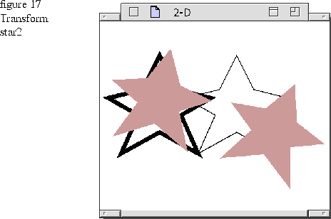
The following code fragment uses a translation matrix to move star2 in the positive x direction by 50 world-coordinate units.
      TGrafMatrix aMatrix2;
      aMatrix.TranslateBy( TGPoint ( 50,0 ) );
      star2->AdoptBundle( new TGrafBundle( TFillBundle( TRGBColor ( .75, .25, .25 ) ) ) );
      star2->TransformBy( aMatrix );
      starGroup->Draw( thePort );
The following code shows how to fill the view with white using the red, green, blue (RGB) color space and specifying a value of TRGB( 1, 1, 1 ) for white.
1  TGArea area;
2  GetAllocatedArea( area );
3
4  TFillBundle fillBundle( TRGBColor( 1, 1, 1 ) );
5
6  thePort.Draw( area.GetBounds(), fillBundle );
Line 4: The white fill bundle defines white in RGB colors.
Line 6: You fill the view with white by calling the Draw function for the port and passing it the area and the fill bundle. The TGArea::GetBounds function returns the smallest rectangle that encloses the area so that only the smallest area is filled with white to reduce overhead and improve performance.